
I. Unit Installation Precautions
1. The unit has been charged with dry nitrogen. Please check before connecting to the system. The unit should use a dedicated power supply and should not share power with other electrical equipment.
2. The grounding bolt is located next to the unit’s control box. Please connect the grounding wire correctly to it to ensure safety. The cross-sectional area of the grounding wire should be the same as the power supply wire.
3. After wiring the unit, the insulation resistance of the circuit to ground must be measured with a 500V megohmmeter. The value should be above 5 megohms.
4. The area around the unit should be well-ventilated. The ambient temperature should be below 38℃. Excessively high ambient temperatures will cause unit malfunction. Avoid direct sunlight. Condensation on the compressor’s return pipe can be drained.
5. The distance between the air-cooled unit and the wall should be no less than 500 mm. The installation foundation of the unit should be flat and firm. The horizontal tilt should not exceed 0.3%.
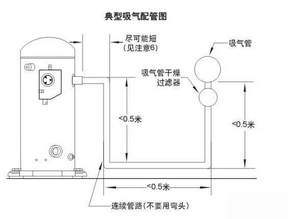
2. Refrigeration System Piping
In Freon systems, the design and installation of the return gas pipe are particularly important. It not only delivers Freon gas to the compressor but also uses the flow velocity of the gas within the pipe to carry the lubricating oil from the evaporator back to the crankcase. Only proper piping can ensure a good oil balance in the system. Installers must ensure that the lubricating oil flows back to the compressor crankcase under all circumstances. Therefore, the following should be noted:
1. Ensure that the pressure drop does not exceed the allowable limit. (Source: Refrigeration Encyclopedia)
2. Ensure that the return gas pipe, especially the riser pipe, maintains a necessary oil carry-over velocity, generally 8 m/s.
3. Prevent unevaporated liquid refrigerant from entering the compressor. Low-temperature systems (evaporation temperature below -40℃) with large load variations should install a vapor-liquid separator.
4. All horizontal suction pipes should be inclined towards the compressor at a slope of 0.3% to facilitate oil return.
5. Piping should not be placed too close to the compressor.
6. Refrigeration high-pressure piping should be as simple and short as possible, avoiding dents in the piping, as these will cause oil buildup.
7. It is recommended to insulate the suction pipe to limit superheat of the suction gas. (Source: Refrigeration Encyclopedia)
8. If the suction pipe is not insulated or condensation is possible, ensure that condensate does not flow into any electrical components, such as the compressor’s junction box. (Source: Refrigeration Encyclopedia)
9. Piping should be reliably secured, especially where it passes through holes or bends. Avoid collisions and friction between the piping and sharp, hard objects.
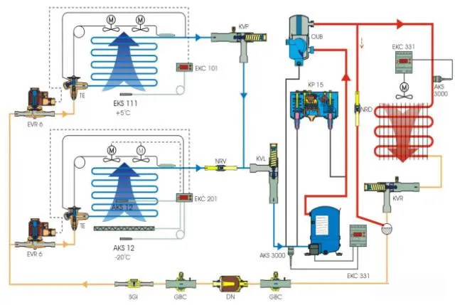
3. Refrigeration System Parts Guide
Expansion Valve Selection:
The choice between internal and external balance depends on the pressure drop in the evaporator. For example, in an R22 system, when the pressure drop exceeds the corresponding evaporation temperature by 1°C, the diaphragm of an internally balanced expansion valve senses the evaporator inlet pressure; while the diaphragm of an externally balanced expansion valve senses the evaporator outlet pressure.
Note: (The introduction and selection of expansion valves has been published multiple times on the Refrigeration Encyclopedia. You can read related articles by entering “expansion valve” in the Refrigeration Encyclopedia dialog box; it will not be repeated here.)
Oil Separator:
The oil separator is installed on the compressor’s discharge pipe. Its function is to separate oil droplets from the gaseous refrigerant and prevent them from entering subsequent parts of the system. There is a float valve at the bottom of the oil separator. When the separated oil deposits reach a certain amount, the float valve will automatically open, and the oil will flow back to the compressor crankcase under the pressure difference. A high-efficiency oil separator can separate more than 90% of the oil droplets from the refrigerant.
Oil separators are recommended to be installed in the following situations:
1. The pipeline distance between the compressor and the evaporator exceeds 30 meters or there are many oil traps.
2. Devices with poor oil return, such as serpentine evaporators.
3. Devices with multiple evaporators or multiple condensers.
4. Units with evaporation temperatures below -30℃.
Sight Glass:
The sight glass allows observation of the refrigerant’s liquid flow and water content. Continuous bubbles indicate poor cooling. A blue water content indicator paper indicates dry refrigerant. Note: If it turns grayish-white, the refrigerant water content has increased, but the unit can still operate. If it turns pink, the dryer filter should be replaced.
Solenoid Valve:
A solenoid valve is installed on the liquid supply line. It is usually synchronized with the compressor’s operation to prevent large amounts of liquid refrigerant from entering the evaporator when the unit stops, reducing the possibility of liquid slugging upon restarting.
Crankcase Heater:
The crankcase heater maintains a higher temperature for the refrigeration oil, reducing the liquid refrigerant content in the oil and preventing oil boiling and migration with the refrigerant during compressor startup, which can cause oil shortage. All normally operating units should use the provided crankcase heater. The standard for effective crankcase heater operation is that the crankcase temperature is at least 10°C higher than the compressor’s saturated return gas temperature.
Note:
1. Power on the crankcase heaters 12 hours before the unit’s first operation.
2. All crankcase heaters operate at 220V.
Vacuum-Liquid Separator:
The function of the vapor-liquid separator is to protect the compressor when liquid refrigerant returns after startup, operation, or defrosting (heat pump). It provides additional internal volume on the low-pressure side of the system, temporarily storing the returning liquid refrigerant and returning it to the compressor at a permissible, controlled rate. This helps protect against refrigerant transfer during shutdown. Vacuum-liquid separators should not be used in non-azeotropic refrigerant systems.
For refrigeration systems with large load variations, selecting a suction vapor-liquid separator with a regenerator can more effectively prevent liquid slugging and also increase the system’s cooling capacity. Vacuum-liquid separators are very effective in preventing damage that may be caused by temporary liquid refrigerant return.

WeChat
Scan the QR Code with wechat