
1. Overview of Water-Cooled Screw Chillers
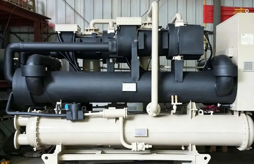
Water-cooled screw chillers are common refrigeration equipment in industrial and commercial air conditioning systems, primarily used in applications requiring large-scale cooling, such as central air conditioning systems in factories, data centers, large commercial buildings, hospitals, hotels, and office buildings. Their working principle is based on a vapor compression refrigeration cycle, using water as the cooling medium.
The structure of a water-cooled screw chiller mainly consists of the following key components:
- Screw Compressor: This is the heart of the chiller. The rotating screw compresses the refrigerant, increasing its pressure and temperature, thus driving the refrigeration cycle.
- Condenser: Used to condense the compressed, high-temperature, high-pressure refrigerant vapor. Circulating cooling water carries away its heat, causing the refrigerant to condense into a liquid state.
- Drier Filter: Used to filter moisture and impurities from the system, protecting the refrigerant and equipment from contamination.
- Expansion valve: Controls the flow rate of refrigerant from the condenser to the evaporator, regulates the refrigerant pressure and state, and ensures effective evaporation.
- Evaporator: Liquid refrigerant absorbs heat from the chilled water and evaporates into a gaseous state, achieving the cooling purpose. The chilled water, after its temperature decreases, is then sent to the user end for further cooling.
- Electrical control section: Includes a PLC or microprocessor control board, display panel, sensors, relays, contactors, protection components, etc., responsible for the automatic control, monitoring, fault diagnosis, protection, and user interface operation of the entire system.
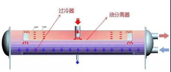
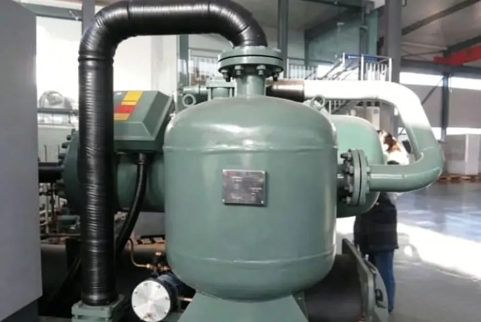
- Oil separator: Separates and recovers refrigerant oil from the refrigerant gas, ensuring oil circulation and protecting the compressor for proper lubrication.
- Power supply and electrical control box: Contains transformers, capacitors, contactors, circuit breakers, fuses, etc., providing a safe and stable power supply to the unit and integrating control logic.
- Auxiliary components: Such as angle valves, pipe connectors, insulation materials, supports, drainage facilities, etc., although not core components, ensure the normal operation and ease of maintenance of the unit.
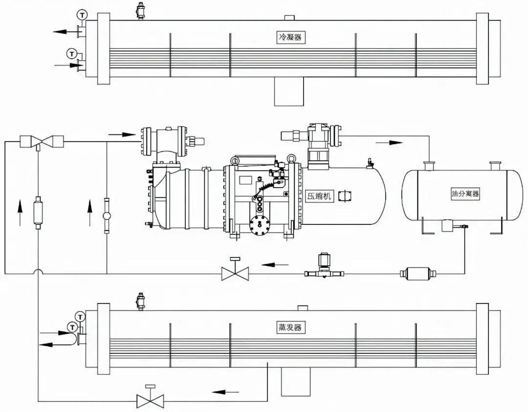
2. Refrigeration System Principle
This unit is based on the vapor compression refrigeration principle, cyclically refrigerating through four key steps (compression, condensation, throttling, and evaporation). The compressor increases the refrigerant pressure and temperature. Cooling water in the condenser removes heat and condenses into a liquid state. Throttling reduces pressure and temperature, allowing the refrigerant to evaporate and absorb heat in the evaporator, achieving continuous refrigeration. The refrigeration capacity is directly proportional to the compressor’s intake capacity, regulated by a slide valve.
Compression Process: After the refrigerant vapor in the evaporator is drawn into the screw compressor, the motor applies energy to it through the compressor rotor, increasing the pressure of the refrigerant vapor and directing it into the condenser. Simultaneously, the temperature of the refrigerant vapor also increases at the end of compression.
Condensation process: High-pressure, high-temperature refrigerant vapor from the compressor releases heat through the cooling water in the condenser, causing its temperature to drop. Simultaneously, under saturation pressure (the condensing pressure corresponding to the condensing temperature), it condenses into a liquid. At this point, the cooling water absorbs heat from the refrigerant vapor, causing its temperature to rise. The temperature of the cooling water is directly related to the condensing temperature (condensing pressure).
Throttling Process: The high-temperature, high-pressure refrigerant liquid from the bottom of the condenser undergoes pressure reduction and expansion as it flows through the throttling device, resulting in a decrease in both pressure and temperature, transforming it into a low-pressure, low-temperature liquid that enters the evaporator.
Evaporation Process: The low-pressure, low-temperature refrigerant liquid absorbs heat from the secondary refrigerant (such as chilled water) in the evaporator and evaporates into gas, simultaneously lowering the temperature of the secondary refrigerant, thus achieving artificial refrigeration. The refrigerant vapor in the evaporator is then drawn into the compressor for compression, repeating the compression, condensation, throttling, and evaporation processes. This cycle continues continuously, achieving the purpose of continuous refrigeration.
Oil Circulation System: Inside the compressor, the refrigerant oil, relying on the system’s high and low pressure differences and through internal oil passages, provides lubrication and cooling to the bearings and rotor. During continuous compressor discharge, the refrigerant oil is discharged from the compressor along with the refrigerant gas. If the discharged refrigerant oil cannot return to the compressor, it may lead to oil loss in the compressor, and in severe cases, damage the compressor. The oil return system ensures that the refrigerant oil discharged with the refrigerant gas smoothly returns to the compressor, ensuring the safe and reliable operation of the unit.
A high-efficiency oil separator is installed between the compressor discharge and the condenser. Most of the refrigerant oil discharged with the refrigerant gas is intercepted by the oil separator and sent directly back to the compressor through the suction port. Alternatively, oil can be returned via high-pressure ejector. A small portion of the refrigerant oil enters the condenser and eventually accumulates in the evaporator. Using high-pressure liquid as a driving force, the accumulated refrigerant oil in the evaporator is carried directly back to the compressor.
Control System Introduction: The control system uses microcomputer control. The control panel is equipped with power, operation, and fault indicator lights, allowing for convenient and intuitive understanding of the unit’s current operating status. In addition, the control panel is equipped with an emergency stop switch. In the event of an emergency failure requiring immediate shutdown, pressing the emergency stop switch ensures the unit’s safety.

WeChat
Scan the QR Code with wechat