
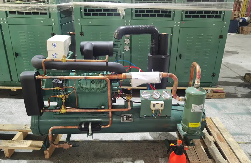
The cold storage refrigeration system is a compression refrigeration system. Through four main processes—compression, condensation, throttling, and evaporation—of the refrigerant cycle, heat is transferred from the inside of the cold storage to the external environment, ensuring a low-temperature environment inside. The following details the components, their functions, and common troubleshooting procedures.
1. Compressor
The compressor draws low-temperature, low-pressure refrigerant gas from the evaporator and compresses it into high-temperature, high-pressure gas through electrical work. This provides the power for the refrigerant cycle and also creates conditions for the refrigerant to condense under high pressure. As the “heart” of the refrigeration system, the compressor’s performance directly affects the overall refrigeration effect. Common compressor types include piston, screw, and scroll compressors. Different types of compressors differ slightly in structure and working principle, but all perform the crucial task of compressing the refrigerant.
2. Vibration Isolation Tubes
The function of vibration isolation tubes: Vibration isolation tubes in cold storage units, also known as vibration absorbers, are mechanical vibration damping elements that absorb vibration noise and reduce unit vibration during operation.
3. Oil Separator
The compressor exhaust enters the oil separator, which typically employs a filter-type or centrifugal structure. The former uses one or more filter layers to intercept oil droplets, while the latter utilizes the centrifugal force generated by the high-speed rotation of the gas to cause denser oil droplets to move towards the separator wall and aggregate for separation. Effective separation of the lubricating oil carried by the refrigerant prevents it from entering subsequent circulation and affecting heat exchange efficiency, while ensuring an adequate oil supply to the compressor’s lubrication system. The separated lubricating oil returns to the compressor via a return oil pipe, which is equipped with an oil filter and an oil level controller. The separation efficiency of the oil separator directly affects the system’s operational stability and the compressor’s lifespan. If the separation effect is poor, excessive lubricating oil will enter the condenser and evaporator, forming an oil film on the heat exchange surfaces and reducing heat exchange efficiency.
4. Oil Filter
Typically a cylindrical structure, it contains a metal filter screen or filter element. The screen traps impurities in the lubricating oil, ensuring the returned oil is clean and preventing wear on internal compressor components, thus extending the compressor’s lifespan. The oil filter element needs regular replacement to maintain its filtering effect. A clogged filter element will obstruct oil flow, affecting the compressor’s lubrication and potentially damaging it.
5. Oil Level Controller
Generally composed of a float, a sensing mechanism, and a control circuit. The float rises and falls with the oil level in the compressor. The sensing mechanism triggers the control circuit. When the oil level is too low, a signal is sent to replenish lubricating oil; when it is too high, oil replenishment stops, ensuring the oil level in the compressor remains stable within a reasonable range. The accuracy of the oil level controller is crucial for the normal operation of the compressor. If the oil level is too low, the compressor may be damaged due to insufficient lubrication; if the oil level is too high, it will increase oil consumption and may even allow lubricating oil to circulate in the refrigeration system, affecting cooling performance.
6. Condenser
High-temperature, high-pressure refrigerant gas enters the condenser, where it exchanges heat with the external cooling medium (water or air), releasing heat and condensing into a high-pressure liquid, thus transferring heat from the refrigerant to the outside environment. Condensers are commonly of two types: air-cooled and water-cooled. Air-cooled condensers use a fan to force airflow to remove heat, while water-cooled condensers dissipate heat through circulating cooling water. The condenser’s heat dissipation effect directly affects the condensing pressure and temperature of the refrigeration system, thereby affecting the overall system’s cooling capacity and energy consumption.
7. Condensing Pressure Regulator
This consists of a pressure sensing element (such as a bellows or diaphragm) and a regulating valve. The sensing element detects changes in condensing pressure and drives the valve to regulate the bypass flow of refrigerant, stabilizing the condensing pressure within a set range. This ensures efficient system operation and prevents excessively high or low pressure from affecting the cooling effect. When the condensing pressure is too high, the regulating valve opens, allowing some refrigerant to bypass, reducing the amount of refrigerant entering the condenser and thus lowering the condensing pressure. When the condensing pressure is too low, the regulating valve closes, increasing the amount of refrigerant entering the condenser and raising the condensing pressure.
8. Refrigerant Receiver
Generally a cylindrical, sealed container used to store the high-pressure liquid condensed from the condenser. Its function is to buffer the refrigerant flow, adapt to system load fluctuations, ensure a continuous and stable supply of liquid to subsequent throttling components, and prevent insufficient liquid supply from affecting the cooling effect. The capacity of the receiver should be rationally designed according to the system’s cooling capacity and operating conditions. Too small a capacity will not meet the needs of system load changes, while too large a capacity will increase system cost and floor space.
9. Dryer Filter
Typically installed on the high-pressure liquid line after condensation, it has a metal outer shell and is filled with a desiccant (such as a molecular sieve) and a filter layer (such as a metal mesh or fiber). When the high-pressure refrigerant flows through, the desiccant adsorbs moisture, and the filter layer intercepts impurities, preventing moisture from causing ice blockage or impurities from clogging pipes and damaging components, thus ensuring the purity of the refrigerant. The dryer filter needs to be replaced regularly to ensure its drying and filtering effect. If the dryer filter fails, moisture and impurities will enter the system, potentially leading to serious consequences such as system blockage and compressor damage.
10. Solenoid Valve
Composed of a solenoid coil, valve core, and valve body. When energized, the solenoid coil generates magnetic force to attract the valve core, opening the valve; when de-energized, the valve core closes the valve under spring force. The solenoid valve receives commands from the temperature control system within the refrigeration unit and precisely controls the flow of refrigerant through the control circuit, thereby regulating the operation and shutdown of the refrigeration cycle. The solenoid valve should operate sensitively and reliably; jamming or leakage will affect the normal operation of the refrigeration system.
11. Sight Glass
The sight glass is a component with a transparent viewing window, typically installed on the high-pressure liquid line after the dryer filter. By observing the refrigerant flow state within the window (e.g., the presence of bubbles, stability of the liquid flow), it is possible to determine whether the refrigerant flow rate is normal and whether there is moisture in the system (bubbles may indicate moisture or insufficient refrigerant), providing a direct basis for monitoring the system’s operating status. When observing the sight glass, a comprehensive judgment should be made based on the system’s operating parameters and actual conditions.
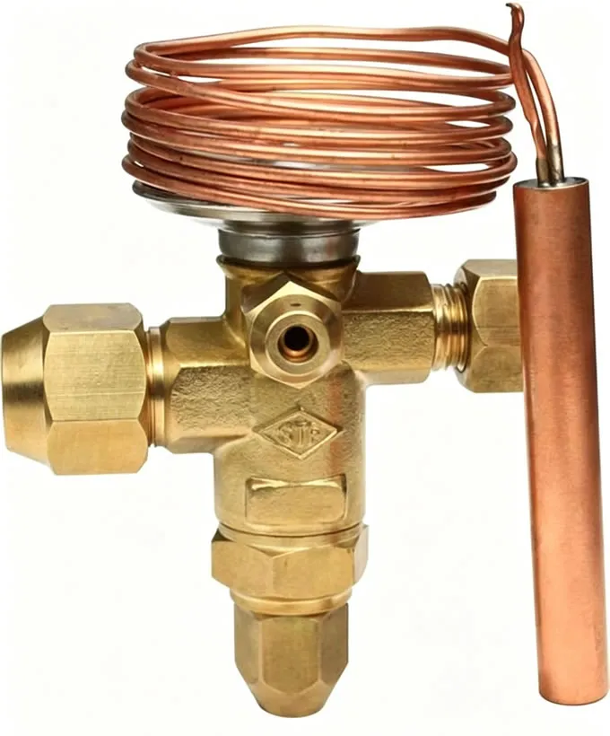
12. Thermostatic Expansion Valve
It consists of a temperature sensing bulb, valve core, regulating mechanism, and valve body. The temperature sensing bulb detects the evaporator outlet temperature, i.e., the superheated gas temperature, and converts it into pressure. This pressure, along with the spring force and evaporation pressure within the valve, counteracts and drives the valve core opening. The expansion valve has three functions: throttling and pressure reduction, superheat control, and refrigerant flow regulation. When high-pressure liquid flows through the narrow channel within the valve, throttling and pressure reduction results in a low-temperature, low-pressure gas-liquid mixture. Simultaneously, the superheat at the evaporator outlet changes with the load, and the expansion valve adjusts its opening accordingly, dynamically regulating the refrigerant flow to ensure optimal heat exchange efficiency within the evaporator. The selection of the thermostatic expansion valve should be based on parameters such as the system’s cooling capacity, evaporation temperature, and condensation temperature. Inappropriate selection can lead to poor system cooling performance or unstable operation.
13. Evaporator
The evaporator is located inside the cold storage room and comes in two forms: direct-cooling pipe coils and indirect-cooling air coolers. Direct-cooling pipe coils have a finned tube structure, consisting of tube bundles, fins, and a frame. Low-temperature, low-pressure refrigerant flows within the tube bundle, increasing the heat exchange area with the air inside the cold storage through the fins, absorbing heat and evaporating into a low-pressure gas, directly achieving the cooling target within the cold storage. Indirect-cooling air coolers force air circulation, allowing heat exchange between the air and the evaporator surface to achieve cooling. Direct-cooling pipe coils provide uniform cooling but have a slower cooling rate; indirect-cooling air coolers provide fast cooling but may result in uneven temperature distribution within the cold storage room.
13. Hot Gas Bypass Valve
This consists of a valve body, valve core, and control mechanism. When the load inside the evaporator is too low, resulting in low evaporation pressure, the control mechanism, based on pressure or temperature signals, drives the valve core to open, bypassing some high-temperature, high-pressure refrigerant gas to the evaporator outlet. This maintains stable evaporation pressure and prevents excessive frost buildup on the evaporator or excessively low compressor suction pressure. The opening and closing pressures of the hot gas bypass valve should be set appropriately according to the system’s operating conditions to ensure stable operation even under low loads.
14. Evaporator Pressure Regulator
Composed of a pressure sensing element (such as a diaphragm) and a regulating valve. The sensing element detects the evaporation pressure and controls the outflow of refrigerant gas from the evaporator by adjusting the valve opening, stabilizing the evaporation pressure and ensuring the evaporation process occurs within a reasonable pressure range, thus improving refrigeration efficiency and system stability. The evaporator pressure regulator ensures that the evaporator maintains a stable evaporation pressure under different load conditions, thereby improving the system’s refrigeration effect and operational stability.
15. Gas-Liquid Separator
Mostly cylindrical in structure, with internal separation elements (such as baffles or spiral blades). Utilizing the principles of gravity and inertia, the liquid refrigerant carried in the low-pressure gas is separated and collected at the bottom of the separator, preventing liquid refrigerant from entering the compressor and causing liquid slugging damage. This ensures that only pure low-pressure gas enters the compressor, avoiding liquid slugging. The separation effect of the gas-liquid separator directly affects the safe operation of the compressor. If the separation is incomplete, liquid refrigerant will enter the compressor, leading to liquid slugging and damage to compressor components.
16. Dryer Filter
The dryer filter is installed on the suction pipe and is mainly used to protect the compressor. Its structure is similar to that of the liquid line dryer filter, filled with desiccant and a filter layer. It performs a second filtration of the low-pressure refrigerant gas, adsorbing any trace moisture and intercepting impurities, protecting the compressor from moisture and impurities, and ensuring a smooth suction process. The dryer filter on the suction pipe also needs to be replaced regularly to maintain its filtration effect.
17. Pressure Controller
It consists of a pressure sensing element (such as a bellows) and a control circuit. The sensing element detects the low-pressure gas pressure. When the pressure reaches the set value, it triggers the control circuit to control the start/stop of the compressor or regulate energy, ensuring that the suction pressure remains within the normal range and maintaining stable system operation. The pressure controller’s set value should be reasonably adjusted according to the system’s operating requirements and the compressor’s performance to ensure that the system operates under safe and stable conditions.
Common Fault Repair Procedures for Cold Storage Units
1. Compressor Faults
Fault Symptoms: Compressor fails to start, emits abnormal noise during operation, discharge pressure is too high or too low, etc.
Repair Methods:
Failure to Start: Check if the power supply is normal; check if the compressor’s starting capacitor, contactor, and other electrical components are damaged; replace them immediately if damaged; check if the compressor’s mechanical parts are stuck; repair or replace if necessary.
Abnormal Noise: Check if the compressor’s mounting bolts are loose; tighten them if loose; check if the compressor’s bearings, connecting rods, and other moving parts are worn; replace them if worn; check for foreign objects inside the compressor; clean them if present.
Excessive Discharge Pressure: Check if the condenser’s heat dissipation is good; if heat dissipation is poor, clean the dust and debris from the condenser surface; check if the cooling water system is normal (for water-cooled condensers); check if there is too much refrigerant in the system; release any excess if present.
1. Low Discharge Pressure: Check if the compressor’s suction pressure is normal. If the suction pressure is too low, check if the evaporator is blocked or frosted. Check for refrigerant leaks; if leaks are found, locate and repair them, and add refrigerant.
2. Condenser Failure
Fault Symptoms: Poor condenser heat dissipation, excessively high condensing pressure, condenser leaks, etc.
Repair Methods:
Poor Heat Dissipation: For air-cooled condensers, check if the fan is operating normally. If the fan is not turning, check if the fan motor, capacitor, and other electrical components are damaged. Replace any damaged components. Clean the dust and debris from the condenser surface to ensure proper airflow. For water-cooled condensers, check if the cooling water flow is normal. If the flow is too low, check if the water pump is working properly and if the cooling water pipes are blocked. Check if the cooling water temperature is too high; if the temperature is too high, adjust the operating parameters of the cooling water system.
High condensing pressure: In addition to checking the condenser’s heat dissipation, check if there is too much refrigerant in the system. If so, release it. Check if the condensing pressure regulator is malfunctioning; if so, repair or replace it.
Condenser leakage: Pressure test the condenser to find the leak point. For small leaks, welding or bonding can be used for repair. For condensers with severe leaks, replacement is necessary.
3. Expansion valve malfunction
Symptoms: Expansion valve blockage, excessive or insufficient opening, unstable refrigerant flow, etc.
Repair methods:
Blockage: Close the shut-off valves before and after the expansion valve, remove the expansion valve, and clean it with refrigerant or nitrogen to remove impurities and dirt. Check if the dryer filter is malfunctioning; replace it if necessary.
Excessive or Insufficient Refrigerant Opening: Check if the expansion valve’s temperature sensor is installed correctly. The sensor should be tightly fitted to the evaporator outlet pipe and properly insulated. Check if the expansion valve’s adjustment mechanism is flexible; repair or replace if stuck. Readjust the expansion valve opening based on the system’s operating parameters and cooling effect.
Unstable Refrigerant Flow: Check if the expansion valve core is worn or loose; replace if worn or loose. Check for air or moisture in the system; purge and dry if present.
4. Evaporator Malfunction
Symptoms: Uneven evaporator frosting, poor cooling effect, evaporator leakage, etc.
Repair Methods:
Uneven Frosting: Check if the hot gas bypass valve, evaporator pressure regulator, and other components are working properly; repair or replace if faulty. Check if the evaporator fan is operating normally; if the fan is not running, check if the fan motor, capacitor, and other electrical components are damaged; replace if damaged. Adjust the evaporator’s airflow and direction to ensure even air circulation within the evaporator.
Poor cooling performance: Check the heat exchange surfaces of the evaporator for dirt or ice; clean if present. Check the refrigerant charge; top up if insufficient. Check the system’s oil return; if obstructed, check the oil separator, oil return pipes, and other components for proper functioning.
Evaporator leakage: Pressure test the evaporator to locate the leak. For finned tube evaporators, welding or repair welding can be used. For aluminum tube evaporators, use specialized adhesive to repair or replace damaged aluminum tubes.
5. Refrigerant leakage fault
Symptoms: Reduced system cooling performance, low compressor suction pressure, low discharge pressure, etc.
Repair methods:
Leak detection: Use a leak detector and other tools to thoroughly inspect the refrigeration system, focusing on pipe connections, valves, compressor, evaporator, condenser, and other components for leaks. For difficult-to-find leaks, use segmented pressure testing to locate them.
Leak Repair: Select an appropriate repair method based on the location and size of the leak, such as welding, bonding, or replacing seals. After repair, a pressure test must be performed again to ensure there are no leaks.
Refrigerant Top-up: After confirming there are no leaks in the system, add the appropriate amount of refrigerant according to the system’s refrigerant charge requirements. When adding refrigerant, pay attention to the type and purity of the refrigerant to avoid introducing impurities and air.
6. Electrical Control System Faults
Fault Symptoms: Compressor cannot start, fan does not turn, temperature controller malfunctions, etc.
Repair Methods:
Compressor cannot start: Check if the power switch is on; check if the fuse is blown, and replace it if blown; check if the contactors, relays, and other electrical components in the control circuit are working properly, and replace them if damaged; check if the compressor’s protection devices (such as overload protectors, pressure controllers, etc.) have activated, and if so, investigate the cause and reset or repair them.
Fan not running: Check if the fan’s power supply is normal; check if the fan’s starting capacitor, motor, and other components are damaged, and replace them if damaged; check if the fan’s control circuit is normal, and repair it if there is a fault.
Temperature controller malfunction: Check if the temperature controller’s set value is correct; check if the temperature sensor is installed in the correct position; check if the temperature controller’s electrical connections are good; if the temperature controller itself is damaged, replace it.

WeChat
Scan the QR Code with wechat